To specify a needle perforating roller, start with the finished-hole requirement, then define the pin layout, working engagement and machine fit. Pin diameter alone does not determine the opening produced in the web.
Brushcustom manufactures custom needle perforating rollers to an approved drawing. This guide explains the decisions behind that drawing and how to identify a replacement when the original specification is incomplete.
What Is a Needle Perforating Roller?
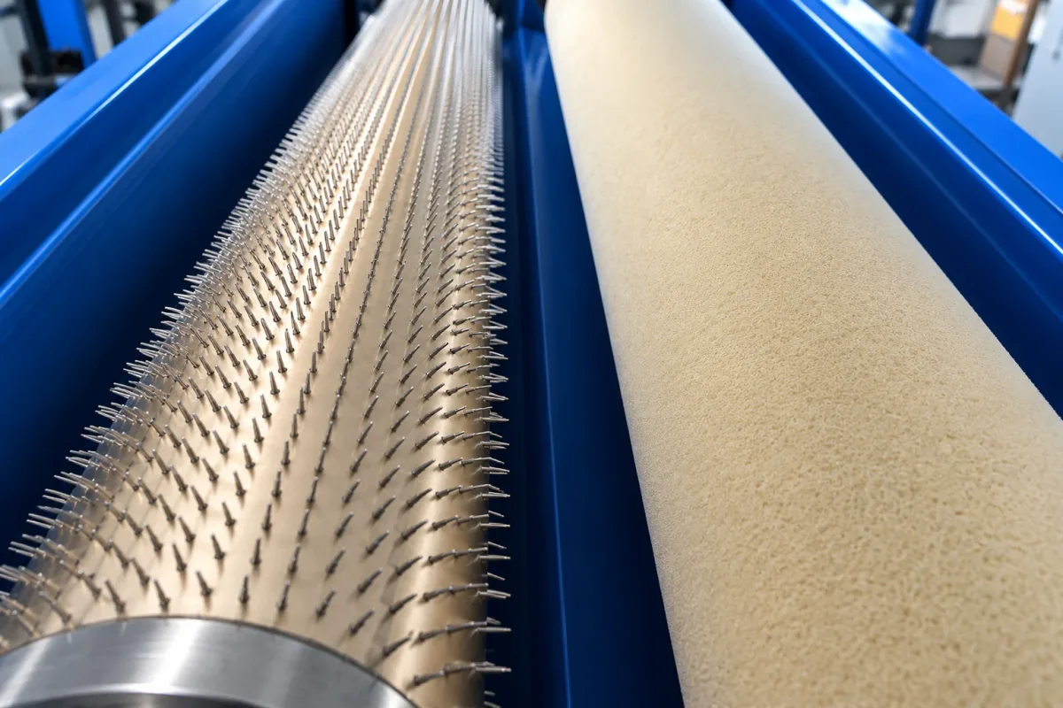
A needle perforating roller is a cylindrical tool fitted with arranged pins. As a moving web passes between the needle roller and a supporting counter roller, the pins create repeated openings. The process can use cold mechanical penetration or heated pins, depending on the material and required result.
Start With the Finished Web Requirement
Define what the perforated material must achieve before selecting the tool:
- Material: web grade, layer construction, thickness and thickness tolerance.
- Working area: total width, perforated width, blank margins and internal unperforated zones.
- Hole result: shape, size range, spacing or density, and acceptable edge condition.
- Performance: the required functional result, test method and acceptance limits.
For packaging film, the target may be ventilation or moisture transfer. For a nonwoven or textile web, it may be air permeability or drainage. Hole count alone does not establish these properties.
ISO 9073-15:2007 provides an air-permeability method for nonwovens. ASTM F1249-25 addresses water-vapor transmission through flexible barrier materials; it is not a default method for every perforated film. The laboratory should confirm suitability for the perforated sample and expected transmission range. Agree on specimen conditioning, test conditions and acceptance criteria before testing.
Choose Between Hot and Cold Needle Perforation
Cold perforation uses mechanical penetration without deliberately heating the needles. It may suit paper, foil, selected films, nonwovens or laminates where heat is unnecessary or undesirable. Tip shape, support and engagement determine whether penetration creates an opening, slit, displaced flap or tear.
Hot needle perforation uses heated pins for compatible thermoplastic webs when heat is needed to form or stabilize the opening. Define the heater interface, operating temperature and control zones with the machine designer. The roller design must also account for its body material, temperature uniformity and dimensional change between room and operating temperature.
Neither process has a universal speed or temperature setting. Trials must use the actual material, thickness and line conditions. Heating and control requirements should come from the machine design, not from another supplier’s published operating values.
Define the Hole Pattern and Roller Pin Layout
Distinguish the required pattern on the finished web from the pin arrangement on the roller:
- Web MD pitch: hole spacing along the machine direction.
- Web CD pitch: hole spacing across the web.
- Roller circumferential pitch: pin spacing around the roller, measured on the developed surface at a specified layout diameter.
- Roller axial pitch: pin spacing along the roller axis.
Do not assume these dimensions transfer unchanged between web and roller. Speed ratio, web stretch and working engagement can affect the finished pattern.
Use a developed flat drawing of the roller surface. Identify the drive end, rotation direction, layout diameter and pattern start datum. Show row offsets and the full repeat cell: rectangular and staggered arrangements can have similar density but different local spacing.
Zones, Margins and Registration
Locate perforated bands, blank lanes and segment joints from a common axial datum. For registered or intermittent perforation, identify the repeat length, angular phase and reference to a keyway, timing mark or control signal. Registration means aligning perforation with a defined feature on the moving web; the roller drawing alone does not define the control system.
Check Full-Circumference Repeats
For a uniformly spaced pattern around the full circumference, an integer number of pins must fit each circumferential row without an unintended final gap:
Angular pitch = 360° ÷ pins per revolution
Developed circumferential pitch = π × pattern layout diameter ÷ pins per revolution
Use the same units for diameter and pitch. If the requested pitch does not divide the circumference evenly, agree which value controls: layout diameter, integer pin count or nominal pitch.
Zoned and nonuniform layouts may contain intentional gaps. Show the complete arrangement and how it crosses or ends at segment joints rather than forcing every gap to be equal.
Calculate Pin Density and Open Area Separately
For a uniform rectangular pin layout, use pitches measured on the developed roller surface at the specified layout diameter:
Pin density (pins/cm²) = 100 ÷ [circumferential pin pitch (mm) × axial pin pitch (mm)]
A 5 mm × 5 mm rectangular layout gives:
100 ÷ (5 × 5) = 4 pins/cm²
For staggered or multi-pin layouts, count the pins in a complete repeat cell and divide by that cell’s developed surface area:
Pin density (pins/cm²) = pins in repeat cell × 100 ÷ repeat-cell area (mm²)
For zoned patterns, state whether density refers to a pinned zone or the whole working surface, including blank areas. Installed pin density is not automatically the number of open holes per unit web area: missed penetration, blocked holes, stretch or slip can change the result.
Estimate Open Area From Finished Holes
For non-overlapping circular openings of measured finished diameter d in millimetres, with N open holes per square centimetre:
Open-area fraction = N × π × (d ÷ 2)² ÷ 100
Open area (%) = Open-area fraction × 100
The denominator of 100 represents the 100 mm² in one square centimetre. This is a geometric estimate, not a permeability or moisture-transmission result. Oval, partly closed or distorted holes require a measurement approach suited to the actual openings.
Specify Pin Geometry and Working Penetration
The pin drawing should identify material, shank diameter, tip profile, projection and fixing method. Include tip angle or radius, position and height tolerances, and orientation where the tip is not rotationally symmetrical.
A shank diameter is not the same as the diameter at the part of a tapered tip entering the web. The finished hole also depends on penetration, material recovery, heat, speed, tension and counter-roller support. Specify a finished-hole range and confirm it on samples.
Projection Is a Tool Dimension; Penetration Is an Operating Setting
Pin projection is measured from a defined roller reference surface to the pin tip. State the measurement direction, target value and permitted variation.
Working penetration depth describes how far the pin enters the web and supporting nip under operating conditions. Record its reference and the machine’s adjustment method. Web thickness, support deformation, runout, load and thermal expansion can change the actual engagement.
Two rollers with identical projection can produce different holes if the nip setting or counter roller changes. Record the approved trial setting and finished-web result separately from the manufactured pin height.
Specify the Counter Roller as Part of the Working Pair
The counter roller supports the web during penetration. Rubber-covered and bristle counter rollers offer different support characteristics; neither is universally better.
| Counter roller | Main selection details |
|---|---|
| Rubber-covered | Covering material, hardness, thickness, surface profile and compatibility with process temperature or chemicals |
| Bristle | Filament material, diameter, trim length, density and working-face construction |
Both need suitable dimensions, mounting and nip adjustment. Evaluate the support and any surface marks on the actual web. Add wear limits or inspection requirements where the application requires them.
Brushcustom can review matching rubber-covered counter rollers and custom cylinder brushes with the needle roller.
Match Roller Speed to the Web Process
Record both web speed and roller RPM. For a machine intended to match the effective roller surface speed to the web, the approximate relationship is:
Roller RPM ≈ 1,000 × web speed (m/min) ÷ [π × effective contact diameter (mm)]
The machine designer must confirm the effective contact diameter. It is not automatically the bare body or pin-tip diameter; working engagement and the machine’s kinematic design matter. The formula does not define settings for intentional slip or a different speed ratio.
Provide the normal and maximum speeds, tension range and drive or synchronization method. For registered or intermittent work, include engagement timing and registration tolerance. Acceleration and stop/start conditions may also matter.
Speed mismatch can stretch the web or elongate holes, while excessive tension can distort thin material even when nominal speeds match. Maximum operating speed must be confirmed for the complete roller and machine arrangement and validated on the actual web.
Define the Construction and Machine Interface
Choose the supply format around the parts that will remain in service:
| Construction | Main fit and replacement questions |
|---|---|
| Complete shafted roller | Shaft ends, bearing seats, drive features and installation clearance |
| Pinned sleeve | Retained shaft condition, bore fit, locking method and removal space |
| Segmented roller | Segment widths, joints, pattern continuity and angular phase |
| Needle rings | Ring widths, spacers, clamping and accumulated axial tolerance |
The drawing should distinguish body diameter, pin-tip outside diameter, working face and overall shaft length. Identify mounting datums and orientation. For wide rollers, include support positions and any mass or handling limits.
Specify runout, concentricity, straightness, balance or other inspection requirements only as applicable to the machine and customer drawing. Agree on tolerances, inspection methods and records before production; they are not identical requirements for every needle roller.
Identify a Replacement Roller Without a Drawing
- Record the installation. Photograph the drive end, counter roller, web path and adjustment mechanism. Note the machine model, roller position and material processed; mark orientation before removal.
- Measure the interfaces. Record body diameter, working width, shaft or bore, journals, keyways and mounting features.
- Map the pin field. Count pins per circumferential row and rows across the face. Record offsets, blank areas and damaged zones; measure projection and photograph the tip under magnification.
- Record the process. Note hot or cold operation, counter-roller type and available speed, tension and engagement settings. Retain an acceptable perforated sample if possible.
- Resolve unknowns by inspection. An old roller or section may be needed to identify hidden construction or pin retention. Do not infer the original tip geometry from badly worn pins alone.
A worn sample is evidence, not automatically the master specification. Separate damage and wear from the required new condition before approving a replacement drawing.
Validate on the Actual Web
Dimensional inspection confirms what was manufactured; it does not prove the finished-hole result. Use representative production material and agree on acceptance before the trial.
- Check the assembly: drawing and orientation, pin condition, counter roller and any agreed dimensional inspections. Follow the machine documentation for setup and controls.
- Record the trial: temperature where relevant, web speed, RPM, tension and penetration setting. Change one variable at a time where practical.
- Sample the result: inspect across the working width and through a complete pattern repeat. Record hole size and shape, edge condition, missing or blocked holes, and zone positions.
- Verify the function: agree on sample locations, acceptance limits and any required permeability, transmission or end-use test.
Food-contact, ESD, cleanroom or special pin-retention requirements need their own applicable criteria and evidence. Do not treat a general material description as proof that the assembled roller meets them.
Frequently Asked Questions
Can an existing needle roller be re-pinned?
Yes, where the body, shaft and interfaces remain suitable. Inspection must establish whether the existing pin fixing can be renewed and the required pattern restored. Re-pinning does not correct an unsuitable or damaged core by itself.
Can Brushcustom supply the complete perforating machine?
No. Brushcustom supplies custom needle perforating rollers and matching counter rollers. Heating systems, controls, guards and complete machines are outside the standard supply scope.
Needle Perforating Roller RFQ Checklist
You do not need every engineering detail to begin. Send these five groups of information, using available measurements:
- Existing tool: drawing or clear photos, plus the required quantity and supply format.
- Web: material, thickness and width.
- Target result: hole pattern or an approved perforated sample, with any functional requirement.
- Machine fit: known roller dimensions and mounting details.
- Process: hot or cold operation, counter-roller type and available speed or tension information.
Brushcustom can review missing details before drawing approval. Send your needle roller inquiry or see our custom needle perforating rollers.